About EZ Schematics: Electrical CAD Software
Whether you're an Electrical Engineer, a Student or an Industrial Maintenance Electrician, there's simply no easier way to draw and print electrical schematic diagrams than with EZ Schematics.
Read our press release.
This software program was designed by an industrial electrician with over 20 years experience in both troubleshooting and training in control relay logic (similar in many regards to PLC logic). The application, established in a line diagram format, provides the end user with the ability to quickly and easily transform
logical concepts into a professionally diplayed electrical
schematic.
Admittedly, as a stand-alone CAD program, EZ Schematics does not
offer all of the features nor the
capabilities of AutoCad and other well established CAD software applications.
But with the learning curve set far lower than the
aforementioned, you'll never find an easier method to transform
electrical relay logic concepts into digital documents (as line
diagrams) that can
be saved and printed with professional appearance.
What makes EZ Schematics a better CAD program for producing electrical schematics includes the following:
1. Ease of use. There's no other Electrical CAD program available that's
easier to learn than EZ Schematics.
2. Almost all of the electrical symbols are created in 1/2" scale increments designed to align perfectly with the default snap (also set at 1/2'),
thus making precise placement of the symbols a simple procedure.
3. Our default library is the NEMA symbols library from which
most U.S. electrical schematics are developed. Thus, there's no waste of time in pouring over thousands of
choices you won't use. We also offer an IEC library.
4. When inserting a symbol, smart choice labeling is employed. For example, when inserting a control relay coil, "CR" is automatically attached as the standard beginning label anticipating it to be followed by "1" or "2", etc.
5. The "Line" control (the most popular device) becomes readily available by simply double-clicking anywhere in the drawing.
6. Labeling the wire numbers is performed easily and precisely. Just click and type at the location of choice.
Never before has there been a CAD program easier to use than
EZ Schematics. If you need to draw electrical schematics and/or
diagrams quickly
and easily, this is a software application you can depend on.

(From the developer) "Being somewhat
proficient in AutoCad myself, I'll choose EZ Schematics any day
of the week over AutoCad for drawing an electrical circuit. When it comes to putting onto paper a concept very
quickly and precisely, our software will win in every case. And
it's because of the simplicity we've built into it. It doesn't
get any easier than this."
In addition to the software being a simple to use CAD
program, its rich features also make it easy to utilize the
program as a training mechanism. Case in point shown below.

In the above circuit, we've highlighted some parts of the
schematic (diagram) in color to demonstrate the principle of voltage
potentials. In this case, all of the high side voltage (120 with
respect to neutral), is displayed in red. The low voltage
(neutral) is represented in blue.
This gives the end user a visual concept and understanding of
the voltage differences (voltage potential) throughout the
circuit. Now the circuit becomes more dimensional in the sense
that it's not just a black and white schematic (diagram), but rather a
more dynamic illustration.
Some of our satisfied customers include:
Advanced Urethane Technologies
American Mfg
Aquion PTY Ltd
Avery Dennison
Bourgault Industries Ltd
Central Arkansas Water
Clear Fork Valley Electric
Corey Compressor
Genpak
Halliburton
Harris Machine Tools
HB-TECHNIK
Husky Corporation
Idaho State University
Kinder Morgan
Knape and Vogt
Lightship Technologies
Parker Hannafin
Schneider Electric
Solar Group
Solar Turbines Incorporated
Super Steel
Superior Roll & Turning LLC
TCI Machinery
Temple Inland
University of Detroit Mercy
Weather Shield
Standard Packaged Symbols Include:
Relay Coil
Normally Open Contact
Normally Closed
Contact
Normally Open Push Button
Normally Closed Push
Button
Mushroom Head Push Button
On Delay Timer, Normally
Open
On Delay Timer, Normally Closed
Off Delay Timer,
Normally Open
Off Delay Timer, Normally Closed
Normally
Open Limit Switch
Normally Closed Limit Switch
Normally
Open Held Closed Limit Switch
Normally Closed Held Open Limit
Switch
Normally Open Pressure Switch
Normally Closed
Pressure Switch
Normally Open Flow Switch
Normally Closed
Flow Switch
Normally Open Float Switch
Normally Closed
Float Switch
Normally Open Temperature Switch
Normally
Closed Temperature Switch
Normally Open Foot Switch
Thermal
Overload
Magnetic Overload
Circuit Breaker
Disconnect
Transformer
Inductor
Fuse
Lamp
Solenoid
Resistor
Reference
Point, 2 Styles
Connection Point
Jumper
2 Position
Selector Switch
3 Position Selector Switch
And more...
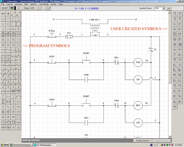
See the image below
You can download
EZ Schematics here, it's free to try.

|